Lab 0: Environment Setup#
Introduction#
In Lab 0, you will prepare the development environment for the future labs. You should install the required toolchain and use it to build a bootable image for OrangePi RV2.
Goals of this lab#
Install the RISC-V toolchain and emulator on your host system.
Learn the fundamentals of cross-platform bare-metal development.
Build and boot a minimal kernel image on QEMU and OrangePi RV2.
Important
This lab is an introductory exercise.
It is not graded, but completing all the Todo parts is essential
to ensure smooth progress in subsequent labs.
Skipping them may result in difficulties later on.
Cross-Platform Development#
Note
This lab is designed and tested primarily on Linux-based systems. While it may be possible to perform the tasks on other platforms (e.g., macOS or Windows with WSL), such environments are not officially supported for now and may introduce unexpected issues. Please proceed with caution if you choose to use a non-Linux environment, and be aware that TA assistance may be limited in such cases.
Cross Compiler#
The Orange Pi RV2 is powered by the Ky X1 System-on-Chip (SoC), featuring an octa-core 64-bit RISC-V processor. To compile your source code to 64-bit RISC-V machine code, you need a cross compiler if you develop on a non-RISC-V environment.
Todo
Install the cross compiler gcc-riscv64-unknown-elf on your host computer.
It is recommended to install it using a package managers like apt.
Alternatively, you can build it from source following the instructions provided by the RISC-V GNU Toolchain project if needed.
Linker#
You might not have explicitly encountered linkers in previous development experiences.
This is because most compilers automatically apply a default linker script
during the build process. (Use ld --verbose to inspect the default script.)
In bare-metal programming, you are responsible for defining the memory layout manually.
The following is a linker script template. You will extend it in a future lab.
SECTIONS
{
    . = 0x80200000;
    .text : { *(.text) }
    .rodata : { *(.rodata) }
    .data : { *(.data) }
    .bss : { *(.sbss) *(.bss) }
}
QEMU#
In cross-platform development, using an emulator can simplify the process of validating your code before testing it on physical hardware. QEMU provides such an environment for early-stage development and testing.
Warning
QEMU provides a machine option virt (a general-purpose virtual board),
but it does not fully replicate the behavior of a real OrangePi RV2 board.
You should always verify your code on actual hardware as well.
Todo
Install qemu-system-riscv64 on your host computer.
From Source Code to Kernel Image#
At this point, you should have a basic understanding of the cross-platform toolchain. The following steps will guide you through using these tools in practice.
From Source Code to Object Files#
Source code is converted to object files by a cross compiler.
After saving the following assembly as a.S,
you can convert it to an object file by riscv64-unknown-elf-gcc -c a.S.
.section ".text"
_start:
  wfi
  j _start
From Object Files to ELF#
A linker links object files to an ELF file. An ELF file can be loaded and executed by program loaders. Program loaders are usually provided by the operating system in a regular development environment. In bare-metal programming, ELF can be loaded by some bootloaders.
To convert the object file from the previous step to an ELF file,
you can save the provided linker script as linker.ld, and run the following command.
riscv64-unknown-elf-ld -T linker.ld -o kernel.elf a.o
From ELF to Kernel Image#
The OS kernel is initially compiled as an ELF file.
To make it suitable for booting, we typically convert it into a raw binary image using objcopy.
This binary image can then be included as part of a Flattened Image Tree (FIT) for use by the bootloader.
riscv64-unknown-elf-objcopy -O binary kernel.elf kernel.bin
Check on QEMU#
After building, you can use QEMU to see the dumped assembly.
qemu-system-riscv64 -M virt -kernel kernel.bin -display none -d in_asm
Todo
Build your first kernel image, and check it on QEMU.
Note
Although QEMU is convenient for early-stage testing, it does not emulate many VF2-specific devices. Do not assume success in QEMU guarantees correct behavior on hardware.
Deploy to OrangePi RV2#
From Kernel Image to FIT Image#
The bootloader on the VF2 board does not typically boot ELF or raw kernel binaries directly. Instead, it expects a single file in the Flattened Image Tree (FIT) format, which packages the kernel image, the device tree blob (DTB), and optionally an initramfs.
To generate a FIT image, you will need the mkimage tool, which is part of the u-boot-tools package.
sudo apt-get install u-boot-tools
You also need to create a configuration file named kernel.its, which specifies
the contents and layout of the resulting FIT image. This file must reference the following components:
kernel.bin– the raw kernel image generated earlierx1_orangepi-rv2.dtb– the device tree for OrangePi RV2initramfs.cpio– an optional root filesystem archive or initialramdisk(not included in this lab; it will be introduced in a later lab. Be sure to remove the corresponding section from the.itsfile for now to avoid build errors)
Below is a minimal example of a valid kernel.its file that includes only the kernel and device tree:
/dts-v1/;
/ {
    description = "U-boot FIT Image for Orange Pi RV2";
    #address-cells = <2>;
    images {
        kernel {
            description = "Kernel Image";
            data = /incbin/("kernel.bin");
            type = "kernel";
            arch = "riscv";
            os = "linux";
            compression = "none";
            load = <0x0 0x00200000>;
            entry = <0x0 0x00200000>;
        };
        fdt {
            description = "Flat Device Tree";
            data = /incbin/("x1_orangepi-rv2.dtb");
            type = "flat_dt";
            arch = "riscv";
            compression = "none";
            load = <0x0 0x31000000>;
        };
    };
    configurations {
        default = "config-1";
        config-1 {
            description = "NYCU OSC RISC-V KERNEL";
            kernel = "kernel";
            fdt = "fdt";
        };
    };
};
The required device tree file can be downloaded from the course resource page.
Once the required files and the kernel.its configuration are prepared,
use the following command to generate the final FIT image:
mkimage -f src/kernel.its kernel.fit
Flash Bootable Image to SD Card#
To boot your VF2 board, you need to write a properly configured bootable image to an SD card.
At minimum, the SD card must contain a FAT16 or FAT32 partition with the following files:
kernel.fit– the FIT image generated in the previous stepvf2_uEnv.txt– the U-Boot environment configuration file for VF2
There are two ways to prepare your SD card:
Method 1: Use a prebuilt image (recommended)
A prebuilt bootable image is available from the course repository.
You can write it to your SD card using the dd command:
sudo dd if=vf2-sdcard.img of=/dev/sdX bs=4M status=progress conv=fsync
Note
The additional parameters are included to improve the usability of the command,
such as speeding up write operations and showing progress.
For detailed explanations, please refer to the dd manual (man dd).
Warning
Replace /dev/sdX with the actual device name of your SD card.
You can check the device name using lsblk.
Writing to the wrong device may cause data loss.
The image is already partitioned, contains the boot firmware, and includes a FAT32 filesystem. You may mount the partition to inspect or modify its contents if needed.
Method 2: Manually create partitions and copy files
You may also manually partition the SD card and install the necessary firmware and files yourself. Detailed instructions for manual setup are available at:
https://hackmd.io/@chiahsuantw/vf2-sdcard
Todo
Use one of the two methods to prepare your SD card for booting VF2.
Interact with OrangePi RV2#
After setting up your SD card and inserting it into the VF2 board, you can interact with the system via UART to verify that your setup is functioning correctly.
The prebuilt kernel included in the image echoes back any characters you type through the serial console.
Follow these steps to test the UART connection:
If you use Method 2 to set up your bootable image, download the kernel binary and place it into the boot partition of your SD card.
Connect a UART-to-USB adapter to your host machine.
Use a serial console program (e.g.,
screen) to open the serial port with the correct settings:
sudo screen /dev/ttyUSB0 115200
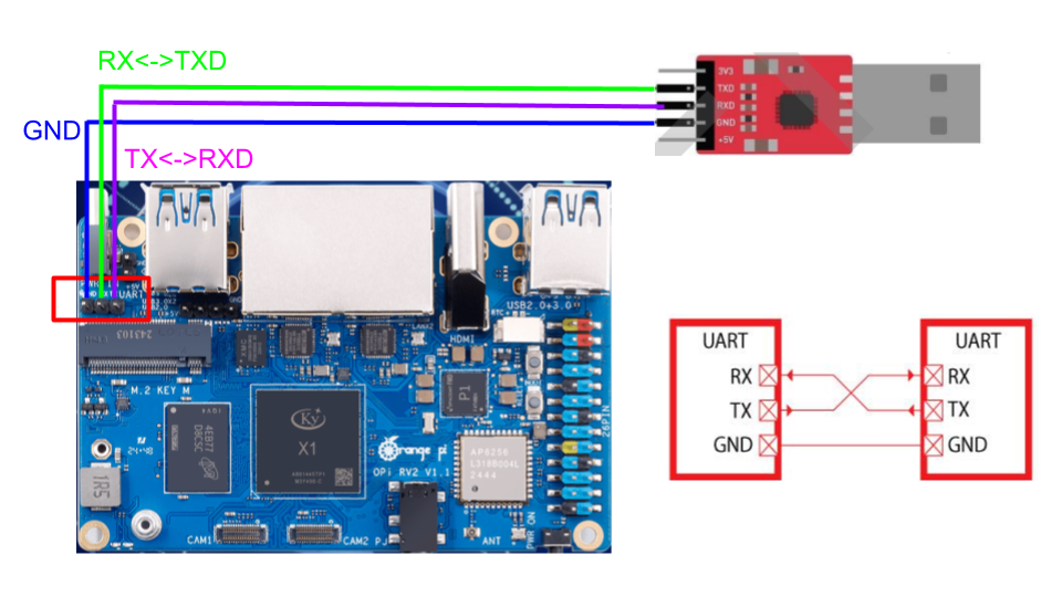
Connect the TX, RX, and GND pins from the UART adapter to the corresponding UART header on the VF2 board. Refer to the diagram below for the correct wiring:
Power on the VF2. Once booted, try typing on your keyboard. You should see the characters echoed back in your serial console.
Note
If nothing appears on the console, double-check the wiring, baud rate, and whether the kernel image was placed correctly.
Debugging#
Debug on QEMU#
QEMU supports basic debugging features such as memory/register inspection and remote debugging with GDB. This allows you to analyze program behavior before deploying to physical hardware.
To begin, install GDB with multi-architecture support on your host machine:
Todo
Install gdb-multiarch on your host computer.
Then launch QEMU in debug mode using the following command:
qemu-system-riscv64 -M virt -kernel kernel.bin -display none -S -s
This starts QEMU in a paused state and opens a debugging port (typically at localhost:1234).
In a separate terminal, start GDB and connect to the running QEMU instance:
gdb-multiarch
(gdb) file kernel.elf
(gdb) target remote :1234
You can now use GDB commands to inspect registers, memory, or step through instructions.
Note
Ensure the kernel.elf file includes debugging symbols (e.g., compiled with -g flag) for full functionality.
Debug on Real VF2#
When working on real hardware, debugging options are more limited. You can insert serial print statements to trace control flow or variable values.
JTAG debugging is not covered in this course, but advanced users with access to JTAG hardware are welcome to explore this option independently.